Floating Neutral
What is floating neutral
A “floating” neutral occurs when the neutral wire, crucial for balancing electrical loads, becomes disconnected or loose. This can happen within the electrical panel or between the utility and the panel due to mechanical failure, corrosion, or other factors. This condition is hazardous because it disrupts the normal voltage distribution across electrical components. As a result, some appliances may receive excessive voltage while others receive insufficient power. In severe cases, outlets can become dangerously energized with full phase-to-phase voltage, posing a significant risk of equipment damage, electric shock, or fire.
With a perfectly balanced load, both the neutral current and voltage are zero. With an unbalanced load, the neutral current is non-zero. In this case, it is the role of the neutral to balance the voltage across the electrical phases. In a floating neutral situation, the phase-to-phase voltages remain normal, but the 0V reference of the neutral gets lost. The larger the load imbalance, the more serious the issue becomes.
Modelling floating neutral in Roseau Load Flow
Roseau Load Flow offers a simple interface for modelling floating neutrals.
Implicit floating neutral
When defining a load, a source, or a transformer with a neutral connection (e.g., 3-phase load with phases “abcn”), on a bus without a neutral port (e.g., 3-phase bus with phases “abc”), the neutral is implicitly floating. This is because the bus doesn’t have a neutral to connect to. The following example shows a load with an implicit floating neutral:
import matplotlib.pyplot as plt
import roseau.load_flow as rlf
from roseau.load_flow.plotting import plot_voltage_phasors

# Define a bus without a neutral
bus = rlf.Bus("Bus", phases="abc")
source = rlf.VoltageSource("Source", bus=bus, voltages=rlf.Q_(400, "V"))
# Define a balanced and an unbalanced load with a neutral. Their neutral is
# implicitly floating because the bus doesn't have a neutral.
z = rlf.Q_(50 + 500j, "ohm")
balanced_load = rlf.ImpedanceLoad("Balanced Load", bus=bus, impedances=z, phases="abcn")
unbalanced_load = rlf.ImpedanceLoad(
    "Unbalanced Load", bus=bus, impedances=[z, 3 * z, 5 * z], phases="abcn"
)
pref = rlf.PotentialRef("PRef", element=bus)
en = rlf.ElectricalNetwork.from_element(bus)
en.solve_load_flow()

fig, axes = plt.subplots(1, 3, figsize=(12, 4))
plot_voltage_phasors(source, ax=axes[0])
plot_voltage_phasors(balanced_load, ax=axes[1])
plot_voltage_phasors(unbalanced_load, ax=axes[2])
plt.show()
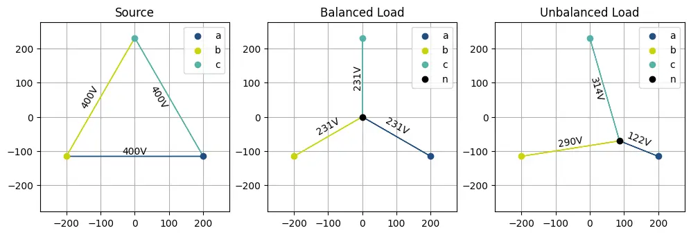
Notice that although the bus doesn’t have a neutral, loads connected to this bus can have a neutral connection. This is because the neutral of a load or source is implicitly considered floating.
The plots of the voltage phasors above show what happens to the potential at the neutral point when the neutral is floating. For the balanced load, the neutral remains at the center of the phasor diagram, while for the unbalanced load, the neutral moves away from the center towards the phase with the lowest impedance. The phase with the highest impedance (i.e with the lowest power) is the one exposed to the highest voltage.
Explicit floating neutral
You can explicitly define a floating neutral by passing connect_neutral=False to the constructor of a load or source
element. This is useful for modelling both elements with floating neutrals and elements with connected neutrals on the
same bus. For transformers, you can explicitly define a floating neutral on the HV side by passing
connect_neutral_hv=False or on the LV side by passing connect_neutral_lv=False. The following example shows how to
create a load with an explicit floating neutral:
import matplotlib.pyplot as plt
import numpy as np
import roseau.load_flow as rlf
from roseau.load_flow.plotting import plot_voltage_phasors

# Define a bus with a neutral
bus = rlf.Bus("Bus", phases="abcn")
source = rlf.VoltageSource("Source", bus, voltages=rlf.Q_(230, "V"))
# Define two unbalanced loads, one with connected neutral and one with floating neutral
z = rlf.Q_(50 + 500j, "ohm") * np.array([1, 3, 5])  # different impedance on each phase
connected_load = rlf.ImpedanceLoad(
    "Load - Neutral Connected", bus, impedances=z, connect_neutral=True
)
floating_load = rlf.ImpedanceLoad(
    "Load - Neutral Floating", bus, impedances=z, connect_neutral=False
)
pref = rlf.PotentialRef("PRef", element=bus)
en = rlf.ElectricalNetwork.from_element(bus)
en.solve_load_flow()

fig, axes = plt.subplots(1, 3, figsize=(12, 4))
plot_voltage_phasors(source, ax=axes[0])
plot_voltage_phasors(connected_load, ax=axes[1])
plot_voltage_phasors(floating_load, ax=axes[2])
plt.show()
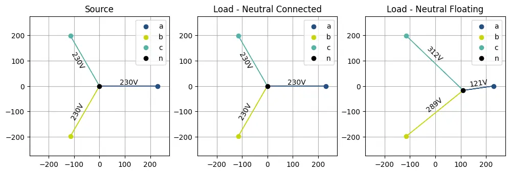
Notice that here even though the bus has a neutral, we can have loads with connected or floating neutrals connected to this bus.
In the plots above, the neutral of the connected load remains at the center of the phasor diagram, even though the load is unbalanced. In this case, the neutral potential is fixed by the source and the voltages remain balanced. On the other hand, the neutral of the load with a floating neutral drifts away from the center towards the phase with the lowest impedance as we saw before.
Note
Passing connect_neutral=True to an element on a bus without a neutral raises an error because the
neutral cannot be connected:
>>> import roseau.load_flow as rlf
>>> bus = rlf.Bus("Bus", phases="abc")
>>> rlf.ImpedanceLoad("Load", bus, impedances=50, phases="abcn", connect_neutral=True)
RoseauLoadFlowException: Phase 'n' of load 'Load' is not in phases 'abc' of its bus 'Bus'. [bad_phase]
In the following example, we show how to create a transformer with a floating neutral on the LV side:
import matplotlib.pyplot as plt
import numpy as np
import roseau.load_flow as rlf
from roseau.load_flow.plotting import plot_voltage_phasors

# Define a MV bus with a source
bus_mv = rlf.Bus("MV Bus", phases="abc")
source = rlf.VoltageSource("Source", bus_mv, voltages=rlf.Q_(20, "kV"))
# Define two LV buses with unbalanced loads
bus1_lv = rlf.Bus("LV Bus 1", phases="abcn")
bus2_lv = rlf.Bus("LV Bus 2", phases="abcn")
z = rlf.Q_(50 + 500j, "ohm") * np.array([1, 3, 5])  # different impedance on each phase
load_tr_connected = rlf.ImpedanceLoad("Unbalanced Load 1", bus1_lv, impedances=z)
load_tr_floating = rlf.ImpedanceLoad("Unbalanced Load 2", bus2_lv, impedances=z)

# Define two Dyn11 transformers with a connected and floating LV neutrals
# For simplicity, we create the transformers from the catalogue
tp = rlf.TransformerParameters.from_catalogue("FT 400kVA 15/20kV(15) 400V Dyn11")
tr_connected = rlf.Transformer(
    "Transformer - Connected Neutral",
    bus_mv,
    bus1_lv,
    parameters=tp,
    connect_neutral_lv=True,
)
tr_floating = rlf.Transformer(
    "Transformer - Floating Neutral",
    bus_mv,
    bus2_lv,
    parameters=tp,
    connect_neutral_lv=False,
)

ground = rlf.Ground("Ground")
pref_mv = rlf.PotentialRef("PRef MV", element=bus_mv)
pref_lv = rlf.PotentialRef("PRef LV", element=ground)
gc_bus1_lv = rlf.GroundConnection(ground=ground, element=bus1_lv)
gc_bus2_lv = rlf.GroundConnection(ground=ground, element=bus2_lv)
en = rlf.ElectricalNetwork.from_element(bus_mv)
en.solve_load_flow()

fig, axes = plt.subplots(2, 2, figsize=(8, 8))
plot_voltage_phasors(tr_connected, side="LV", ax=axes[0, 0])
plot_voltage_phasors(load_tr_connected, ax=axes[0, 1])
plot_voltage_phasors(tr_floating, side="LV", ax=axes[1, 0])
plot_voltage_phasors(load_tr_floating, ax=axes[1, 1])
plt.show()
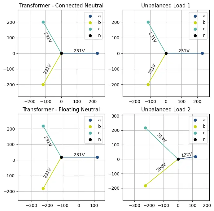
In the plots above, the neutral of both loads remain at 0V as defined by the ground they are connected. The neutral of the transformer with a connected neutral also remains at 0V while the neutral of the transformer with a floating neutral drifts away from 0V. In both cases, the voltages of the transformer remain balanced as they are fixed by the MV source.