Voltage source
Definition
It represents an ideal voltage source that maintains a fixed voltage independently of the load resistance or the output current.
Connections
A voltage source can be either star-connected or delta-connected depending on whether its phases include a neutral or not.
Star (wye) connection
The diagram of the star voltage source is:
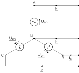
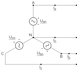
The equations that model a star voltage source are:
Where \(\underline{U}\in\mathbb{C}^3\) is the voltage vector (user defined parameter) and \(\underline{V}\in\mathbb{C}^4\) is the node potentials vector (variable).
Note
You can create star connected sources even on buses that don’t have a neutral. In this case, the source’s neutral will be floating and its potential can be accessed similar to normal star sources.
Delta connection
The diagram of the delta voltage source is:
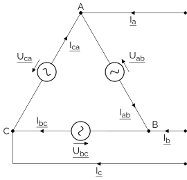
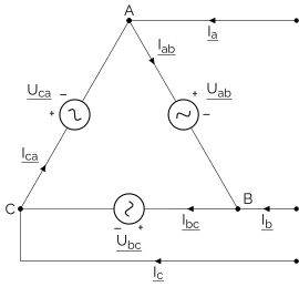
The equations that model a delta voltage source are:
Where \(\underline{U}\in\mathbb{C}^3\) is the voltage vector (user defined parameter) and \(\underline{V}\in\mathbb{C}^3\) is the node potentials vector (variable).
Available Results
The following results are available for all sources:
Result Accessor |
Default Unit |
Type |
Description |
|---|---|---|---|
|
\(V\) |
complex array |
The potentials of each phase of the source |
|
\(A\) |
complex array |
The line currents flowing into each phase of the source |
|
\(V\!A\) |
complex array |
The line powers flowing into each phase of the source |
|
\(V\) |
complex array |
The phase-to-neutral voltages if the source has a neutral, the phase-to-phase voltages otherwise |
Additionally, the following results are available for sources with a neutral:
Result Accessor |
Default Unit |
Type |
Description |
|---|---|---|---|
|
\(V\) |
complex array |
The phase-to-neutral voltages of the source |
And the following results are available for sources with more than one phase:
Result Accessor |
Default Unit |
Type |
Description |
|---|---|---|---|
|
\(V\) |
complex array |
The phase-to-phase voltages of the source |
And the following results are available for three-phase sources:
Result Accessor |
Default Unit |
Type |
Description |
|---|---|---|---|
|
\(\%\) |
number |
The voltage unbalance of the source according to the IEC, IEEE or NEMA definition |
|
\(\%\) |
number |
The Current Unbalance Factor (CUF) of the source |
Usage
A voltage source defined with a neutral phase is a star-connected voltage source, otherwise it is a delta-connected voltage source. The phases of the source must be a subset of the phases of the bus it is connected to. A voltage source takes the same phases as the bus by default.
import numpy as np
import roseau.load_flow as rlf

bus = rlf.Bus(id="bus", phases="abcn")
# The phases of the source are the same as the bus by default
vs1 = rlf.VoltageSource("vs1", bus=bus, voltages=230)  # phases="abcn" implied
vs1.phases  # "abcn"
vs1.voltage_phases  # ["an", "bn", "cn"]

# Explicitly define the phases of the source (star connection)
vs2 = rlf.VoltageSource("vs2", bus=bus, phases="abcn", voltages=230)  # Same as vs1
vs2.phases  # "abcn"
vs2.voltage_phases  # ["an", "bn", "cn"]

# Explicitly define the phases of the source (delta connection)
vs3 = rlf.VoltageSource("vs3", bus=bus, phases="abc", voltages=400)
vs3.phases  # "abc"
vs3.voltage_phases  # ["ab", "bc", "ca"]

# Incorrect phases: the source's phases must be a subset of the bus's phases
bus2 = rlf.Bus(id="bus2", phases="an")
rlf.VoltageSource("vs4", bus=bus2, phases="bn", voltages=230)  # Error
A scalar (potentially complex) voltage value can be used to define the source’s balanced voltages. For a single-phase source, the scalar value is used as the voltage of the source’s phase. For a two-phase source, the second voltage value is the negative of the first value (180° phase shift). For a three-phase source, the second and third values are calculated by rotating the first value by -120° and 120°, respectively (120° phase shift clockwise).
bus = rlf.Bus(id="bus", phases="abcn")

# Three-phase connection (star)
# -----------------------------
rlf.VoltageSource("vs1", bus=bus, phases="abcn", voltages=230)
# {'an': (230+0j), 'bn': (-115-199.18584287042083j), 'cn': (-115+199.1858428704209j)}

# Three-phase connection (delta)
# ------------------------------
rlf.VoltageSource("vs2", bus=bus, phases="abc", voltages=400)
# {'ab': (400+0j), 'bc': (-200-346.41016151377534j), 'ca': (-200+346.4101615137755j)}

# Two-phase connection
# --------------------
rlf.VoltageSource("vs3", bus=bus, phases="abn", voltages=230)
# {'an': (230+0j), 'bn': (-230+0j)}

# Single-phase connection
# -----------------------
rlf.VoltageSource("vs4", bus=bus, phases="an", voltages=230)
# {'an': (230+0j)}

# Unbalanced source, explicit voltage vector
# ------------------------------------------
rlf.VoltageSource(
    "vs5",
    bus=bus,
    phases="abcn",
    voltages=[230, 115 * np.exp(1j * np.pi / 2), 115 * np.exp(-1j * np.pi / 2)],
)
# {'an': (230+0j), 'bn': (115j), 'cn': (-115j)}

# Incorrect voltage vector: only two elements!!
rlf.VoltageSource(
    id="vs6", bus=bus, phases="abc", voltages=400 * np.exp([0, -2j * np.pi / 3])
)  # Error
A voltage vector (list or numpy array) can be used to create an unbalanced voltage source if needed. The voltage vector must have the same size as the number of the phase-to-phase or phase-to-neutral connections of the source.
bus = rlf.Bus(id="bus", phases="abcn")

# Unbalanced source, explicit voltage vector
# ------------------------------------------
rlf.VoltageSource(
    "vs1",
    bus=bus,
    phases="abcn",
    voltages=[230, 115 * np.exp(1j * np.pi / 2), 115 * np.exp(-1j * np.pi / 2)],
)
# {'an': (230+0j), 'bn': (115j), 'cn': (-115j)}

# Incorrect voltage vector: only two voltage values!!
rlf.VoltageSource(
    id="vs2", bus=bus, phases="abc", voltages=400 * np.exp([0, -2j * np.pi / 3])
)  # Error
API Reference
- class VoltageSource(id, bus, *, voltages, phases=None, connect_neutral=None)
A voltage source fixes the voltages on the phases of the bus it is connected to.
The source can be connected in a wye or star configuration (i.e with a neutral) or in a delta configuration (i.e without a neutral).
See also
The Voltage source documentation page for example usage.
Voltage source constructor.
- Parameters:
id (Id) – A unique ID of the voltage source in the network sources.
bus (Bus) – The bus of the voltage source.
voltages (ComplexScalarOrArrayLike1D) –
A single voltage value or an array-like of the voltages of the source to be fixed on the connected bus phases. If the source has a neutral connection, the voltages are considered phase-to-neutral voltages, otherwise they are the phase-to-phase voltages. Either pass complex values (V) or a
Quantityof complex values.When a scalar value is passed, it is interpreted as the first value of the source voltages vector. The other values are calculated based on the number of phases of the source. For a single-phase source, the passed scalar value is used. For a two- phase source, the second voltage value is the negative of the first value (180° phase shift). For a three-phase source, the second and third values are calculated based on the first value and the phase shift of -120° and 120°, respectively (120° phase shift clockwise).
phases (str | None) – The phases of the source. A string like
"abc"or"an"etc. The bus phases are used by default. The order of the phases is important. For a full list of supported phases, see the class attributeallowed_phases. All phases of the source must be present in the phases of the connected bus. Multiphase sources are allowed to be connected to buses that don’t have a neutral ifconnect_neutralis not set toTrue.connect_neutral (bool | None) – Specifies whether the source’s neutral should be connected to the bus’s neutral or left floating. By default, the source’s neutral is connected when the bus has a neutral. If the bus does not have a neutral, the source’s neutral is left floating by default. To override the default behavior, pass an explicit
TrueorFalse.
- element_type: Final = 'source'
The type of the element. It is a string like
"load"or"line"etc.
- type: Final = 'voltage'
- property voltages: Q_[ComplexArray]
The complex voltages of the source (V).
Setting the voltages will update the source voltages and invalidate the network results.
Note
Setting a scalar value updates the complex voltages of all phases of the source, not just their magnitudes. The phase angles are calculated based on the number of phases of the source. For a single-phase source, the phase angle is 0°. For a two-phase source, the phase angle of the second phase is 180°. For a three-phase source, the phase angles of the second and third phases are -120° and 120°, respectively (120° phase shift clockwise).
- Return type:
- disconnect()
Disconnect this element from the network. It cannot be used afterwards.
- Return type:
None
- property res_currents: Q_[ComplexArray]
The load flow result of the element currents (A).
- Return type:
- property res_powers: Q_[ComplexArray]
The load flow result of the “line powers” flowing into the element (VA).
- Return type:
- res_current_unbalance()
Calculate the current unbalance (CU) on this element.
The calculation depends on the definition of current unbalance:
Current Unbalance Factor (CUF):
\(CUF = \dfrac{I_\mathrm{2}}{I_\mathrm{1}} \times 100 \, (\%)\)
Where \(I_{\mathrm{2}}\) is the magnitude of the negative-sequence (inverse) current and \(I_{\mathrm{1}}\) is the magnitude of the positive-sequence (direct) current.
- allowed_phases: Final
The allowed phases for a terminal element are:
P-P-P or P-P-P-N:
"abc","abcn"P-P or P-P-N:
"ab","bc","ca","abn","bcn","can"P-N:
"an","bn","cn"
- property res_potentials: Q_[ComplexArray]
The load flow result of the element potentials (V).
- Return type:
- property res_voltages: Q_[ComplexArray]
The load flow result of the element voltages (V).
If the element has a neutral, the voltages are phase-to-neutral voltages for existing phases in the order
[Van, Vbn, Vcn]. If the element does not have a neutral, the voltages are phase-to-phase for existing phases in the order[Vab, Vbc, Vca].See also
res_voltages_pp: The phase-to-phase voltages of the element. Raises if the element has only one phase.res_voltages_pn: The phase-to-neutral voltages of the element. Raises if the element does not have a neutral.
- Return type:
- property res_voltages_pp: Q_[ComplexArray]
The load flow result of the element’s phase-to-phase voltages (V).
Raises an error if the element has only one phase.
See also
res_voltages: Get the voltages in the natural representation of the element (phase-to-neutral if it has a neutral, phase-to-phase otherwise).res_voltages_pn: The phase-to-neutral voltages of the element. Raises if the element does not have a neutral.
- Return type:
- property res_voltages_pn: Q_[ComplexArray]
The load flow result of the element’s phase-to-neutral voltages (V).
Raises an error if the element does not have a neutral.
See also
res_voltages: Get the voltages in the natural representation of the element (phase-to-neutral if it has a neutral, phase-to-phase otherwise).res_voltages_pp: The phase-to-phase voltages of the element. Raises if the element has only one phase.
- Return type:
- res_voltage_unbalance(definition='VUF')
Calculate the voltage unbalance (VU) on this element.
- Parameters:
definition (Literal['VUF', 'LVUR', 'PVUR']) –
The definition of the voltage unbalance, one of the following:
VUF: The Voltage Unbalance Factor defined by the IEC, also called the “True Definition” (default):\(VUF = \dfrac{V_\mathrm{2}}{V_\mathrm{1}} \times 100 \, (\%)\)
Where \(V_{\mathrm{1}}\) and \(V_{\mathrm{2}}\) are the magnitudes of the positive-sequence and negative-sequence voltages, respectively.
LVUR: The Line Voltage Unbalance Rate defined by NEMA:\(LVUR = \dfrac{\Delta V_\mathrm{Line,Max}}{\Delta V_\mathrm{Line,Mean}} \times 100 (\%)\).
Where \(\Delta V_\mathrm{Line,Mean}\) is the arithmetic mean of the line voltages and \(\Delta V_\mathrm{Line,Max}\) is the maximum deviation between the measured line voltages and \(\Delta V_\mathrm{Line,Mean}\).
PVUR: The Phase Voltage Unbalance Rate defined by IEEE:\(PVUR = \dfrac{\Delta V_\mathrm{Phase,Max}}{\Delta V_\mathrm{Phase,Mean}} \times 100 (\%)\).
Where \(\Delta V_\mathrm{Phase,Mean}\) is the arithmetic mean of the phase voltages and \(\Delta V_\mathrm{Phase,Max}\) is the maximum deviation between the measured phase voltages and \(\Delta V_\mathrm{Phase,Mean}\).
- Returns:
The voltage unbalance in percent.
- Return type:
- is_multi_phase: Final = True
Is the object multi-phase?
- property network: _N_co | None
Return the network the element belong to (if any).
- Return type:
_N_co | None
- id
- to_dict(*, include_results=True)
Convert the element to a dictionary.
- to_json(path, *, include_results=True, indent=True)
Save this element to a JSON file.
Warning
If the file exists, it will be overwritten.
- Parameters:
path (StrPath) – The path to the output file to write the network to.
include_results (bool) – If True (default), the results of the load flow are included in the JSON file. If no results are available, this option is ignored.
indent (bool) – If True (default), the JSON output is pretty-printed with 2-space indentation. Set to False for compact output.
- Returns:
The expanded and resolved path of the written file.
- Return type:
- results_to_dict(full=False)
Return the results of the element as a dictionary.
The results dictionary of an element contains the ID of the element, its phases, and the result. For example, bus.results_to_dict() returns a dictionary with the form:
{"id": "bus1", "phases": "an", "potentials": [[230.0, 0.0], [0.0, 0.0]]}
Note that complex values (like potentials in the example above) are stored as list of [real part, imaginary part] so that it is JSON-serializable
Using the full argument, bus.results_to_dict(full=True) leads to the following results:
{"id": "bus1", "phases": "an", "potentials": [[230.0, 0.0], [0.0, 0.0]], "voltages": [[230.0, 0.0]]}
The results dictionary of the network contains the results of all of its elements grouped by the element type. It has the form:
{
    "buses": [bus1_dict, bus2_dict, ...],
    "lines": [line1_dict, line2_dict, ...],
    "transformers": [transformer1_dict, transformer2_dict, ...],
    "switches": [switch1_dict, switch2_dict, ...],
    "loads": [load1_dict, load2_dict, ...],
    "sources": [source1_dict, source2_dict, ...],
    "grounds": [ground1_dict, ground2_dict, ...],
    "potential_refs": [p_ref1_dict, p_ref2_dict, ...],
}
where each dict is produced by the element’s results_to_dict() method.
- results_to_json(path, *, full=False, indent=True)
Write the results of the load flow to a json file.
Warning
If the file exists, it will be overwritten.
- Parameters:
path (StrPath) – The path to the output file to write the results to.
full (bool) – If True, all the results are added in the resulting dictionary, including results computed from other results (such as voltages that could be computed from potentials). False by default.
indent (bool) – If True (default), the JSON output is pretty-printed with 2-space indentation. Set to False for compact output.
- Returns:
The expanded and resolved path of the written file.
- Return type: